Back to the basics, here is an explanation of why a reversing loop is not a big challenge in DCC, if using the appropriate electronic modules.
The challenge
Reversing loops are a problem for anyone running a 2-rail layout. Only 3-rail systems (such as Märklin) do not have this problem: the tracks are “symmetric”, so there is no short circuit when building a loop.
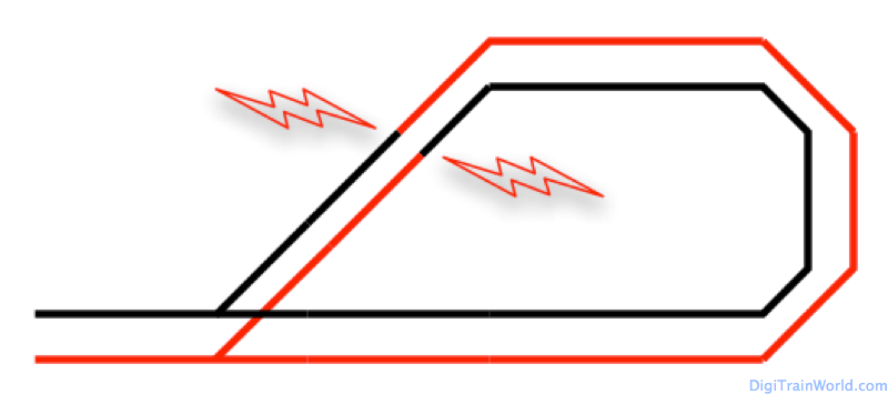
In N-scale, HO and all others, it is pretty easy to see why a reversing loop can be a problem:
The manual solution
There are of course ways to handle a loop manually. For example, one can isolate the core of the loop, and attach is to a switch. One can even link the loop polarity to the turnout, so that the polarity is changed with the turnout position. This change could be manual, or handled by a set of complicated detectors at the entries (magnets, infrared).
All these solutions are fine, but they really are more complicated than they should, especially if you are running in DCC. Why is that? Because as we know, in DCC (and other digital systems), the polarity of the track does not influence the direction of the train. We don’t actually need to worry about which track side is “+” and which track side is “-“, all we need to worry about is to avoid a short circuit and to allow trains to run without a stop.
In order to handle loops properly in DCC, we need a small electronic module. This module will take care of the loop automatically for us, so we never have to worry about the loop again (except maybe the turnout).
Here are the 2 types of modules you could choose.
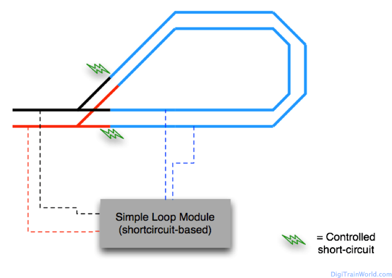
Short-Circuit based modules
The principle of short-circuit based module is to fight fire with fire.
- The loop is isolated from the rest of the layout, and the loop module “watches” it.
- The loop is always powered (in 1 of 2 possible ways)
- As soon as a train enters the loop (on either side), if a short-circuit occurs, the loop modules immediately changes the polarity of the loop. If no short circuit occurs, the train enters the loop normally.
- When the train reaches the end of the loop, another short circuit occurs, and again, the module switches the loop polarity to match the exit of the loop.
I have personally tested one of these modules, and have also read a lot about them. Shortly put: they work OK, and they are cheap.
However, the very principle of using a short circuit to avoid short circuit is not optimal. You may run (and I have run) into one of those 2 issues:
- A cheap module may not detect the short circuit quickly enough before changing the polarity. The short circuit will reach your command station, which will deactivate the layout as a safety.
- Because there is a short circuit, very sensible decoders in trains may be in danger. Although this is a purely theoretical issue (I have never faced it), it is worth considering.
Detection-based modules
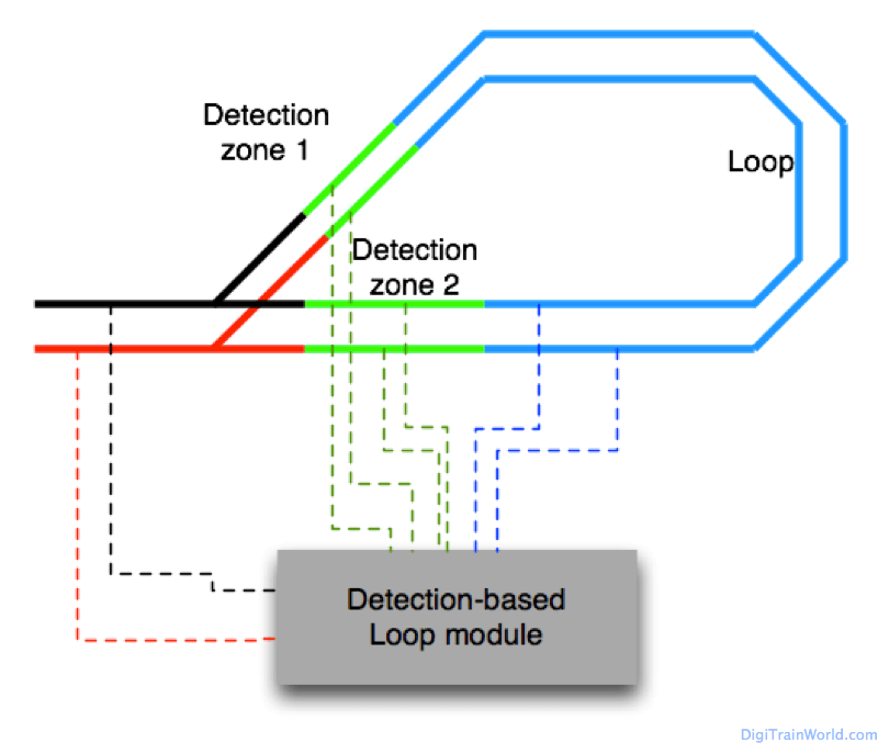
The second, and best type of loop modules, is based on a safer operating principle:
- There are two entry/exit zones. Those zones are usually not powered.
- When a train enters the loop in the entry zone, the module recognises the polarity. It activates both the entry zone and the loop core with the right polarity.
- When the train reaches the exit zone, the module activates the later and reverses the polarity of the entire loop (in which the train still is).
The whole process works without a single short-circuit, fully automatically. This is by far the safest way to operate a returning loop in DCC.
That said, those modules are a bit more expensive and there are more track sections to separate & wires to connect.
Conclusion
If you are running your trains in DCC, I strongly advise using detection based modules. Even if the cheap short circuit modules may work for a while, it is more of a stop-gap measure.
There are many modules on the market, and sometimes the manufacturers are not clear about which type of module it is. You can differentiate the modules fairly easy:
- Short-circuit based modules usually have only 4 connectors (such as this one)
- Detection-based modules will have at least 8 connectors (such as this one)
I personally use the modules from “LDT“, a small German manufacturer (the one mentioned above), and I have no problem whatsoever. Any module based on the same principle should also make your reversing loop life much easier!




Pierre,
I need your help. How do you address the DCC wiring and insulated rails for this diamond crossing configuration? I have them on my layout.
Hi Jimmy, that’s a nice crossing! I like Peco track, but the crossing are notoriously difficult to wire (as opposed to many other brands…where you don’t have to wire anything). I only have the “scissors crossing”, so I can’t help you directly.
However, looking at picture 6 of the manual http://www.peco-uk.com/imageselector/Files/Instruction%20sheets/N%20Electrofrog%20Turnouts.pdf It seems you need 2 single switches PER crossing. Usually these switches are linked to your usual track wires (e.g. red black). In your case, my guess is: the switches for the “center” crossings (the 2 that are side by side) will have to dependent (connected) to the switches of the “extremity” switches (top, respectively bottom switch).
Those “switches” can be either mechanical (linked to whichever motor option you have chosen for the crossings), electromechanical (a relay, separate from the motor but switched at the same time), or even DCC (e.g. a relay decoder, switched by the same address). For my scissor crossing, I am personally using the ESU Switchpilot decoder + the Switchpilot extension (which contains the relays).
Let me know if that helps you a little. In any case it’s gonna be a small challenge!
Pierre, thanks a lot. I take a closer look at the instruction and try to figure out. It is easy when you have one but with 4 interconnected, I am kicking myself on the butt for making it so complex.
You can visit my blog germaN160.wordpress.com for full track plan. Looking forward to your comments too.
Hello Pierre,
Thank you for this article, it was a big help to me. I like the detection loop modules and was curious as to whether you have learned of any products make in Canada or the United States?
Thank you and Happy New Year.
Hi John,
Unfortunately I am not aware of any American alternative. In fact I remember a discussion on a forum where it seemed detection bases modules were relatively unknown on your side of the pond.
I’m pretty sure there is something, can’t tell you where :-/
If budget/time is not an issue, there is always the possibility to order from the EU, here for example http://www.conrad.com/ce/en/product/248035/LDT-KSM-SG-B-Terminal-loop-module-KSM-SG?ref=searchDetail (since the free trade agreement between our continents is still in the works, beware of potential additional import duties!)
Sorry I can’t be of much help!
Happy new year too!
The link above is a DIY kit to solder. Here is the ready to use module: http://www.conrad.com/ce/en/product/248036/LDT-KSM-SG-F-Double-loop-module-for-DDCMM
Hi there,
Thank you for such a great and concise explanation of the loop principle. I have got two questions on the top of that:
1. Is there any requirement for the length of detection zones? What is the best practice?
2. Does the loop (blue section) need to be minimum as long as the longest train or not?
Thanks in advance for your answer.
Filip