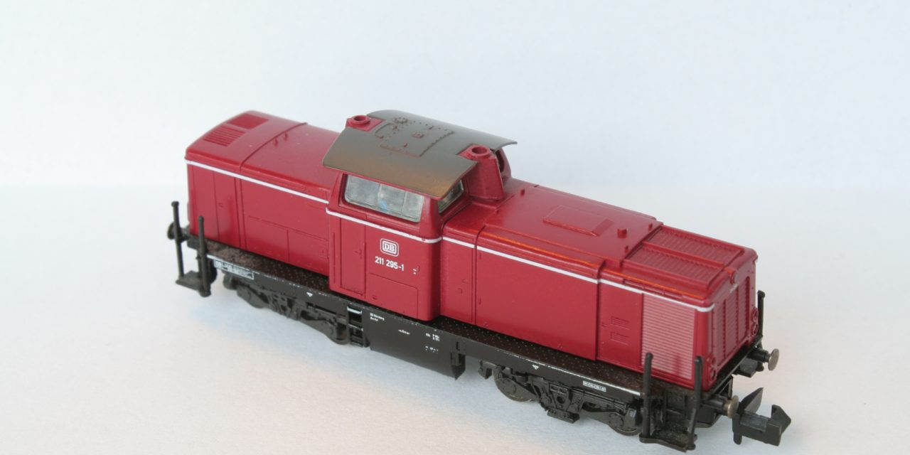
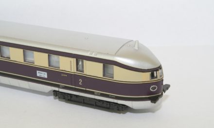
The Fleischmann V100 is a classic. In fact, my model is about 12-15 years old. It was time to improve it.
Functions, functions, functions
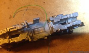
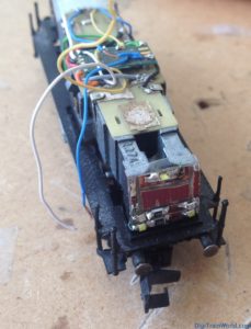
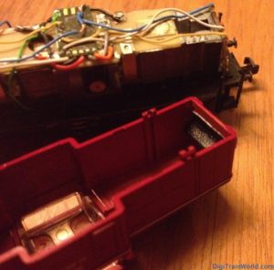
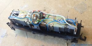
Despite its age, this model has a solid construction. I had it converted to DCC, about 10 years ago. It was time to change everything. New lights, new decoder, here is what I added:
- Doehler & Haass DH05C decoder (review here)
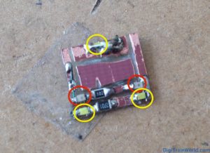
- Triple white LEDs for front lights (outputs “light front/light rear” of decoder)
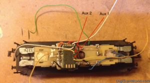
- Double red LEDs for rear lights (outputs “Aux1” and “Aux2” of decoder)
- 4x100uF capacitors for a smoother ride on dirty tracks
- Driver cab lighting (output “Aux 3” of decoder, more on that later).
Technical details
The DH05C decoder is small and limited in total power output. It is however powerful enough for small engines, and has many outputs.
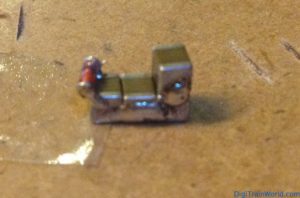
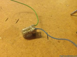
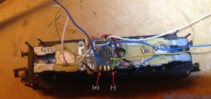
I connected 4x 100uF capacitors from 1001-digital.de in Germany. These are super small. They are limited to 16V, so you need to connected a 16V Zener diode in parallel to protect them (my track power is set to 14V anyway).
Also, as recommended when buffering decoders with capacitors, I added a 100ohm resistor with a Schottky diode before the capacitors. This prevents the capacitors from “charging” too fast (drawing too much power from track instantly), but allows the power to flow back unimpaired to the decoder when needed.
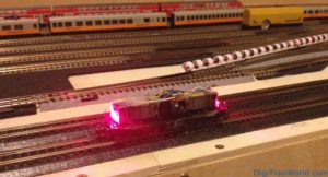
The lights are all connected on individual outputs (4 in total). Such a setup is rare with store-bought N scale models. Usually, the front white lights are connected to the rear red lights, and vice versa. Why is that a problem? Because when the locomotive is attached to cars or coaches, the lights on the convoy side are supposed to be off !
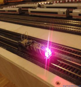
With each lighting block on an independent output, one can achieve 100% realistic lighting. Details in the video:
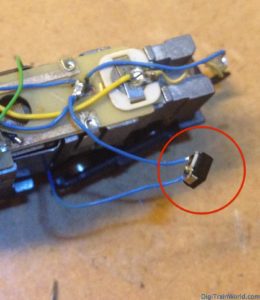
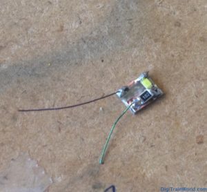
Last but not least, I added a single led to be able to switch the driver cabin on. The DH05C with the latest firmware model was perfect for this. The SUSI output, usually designed to connect sound modules, can be repurposed as 2 additional outputs (Aux 3 and Aux 4). Be careful though: those 2 outputs are NOT amplified (they are “logic” outputs). Usually, you would need a transistor to amplify the outputs, otherwise, the decoder would burn. In my case however, my LED with a resistor will draw about 5-8 mA. This is very low, and I assumed (apparently correctly), that the output could handle it.
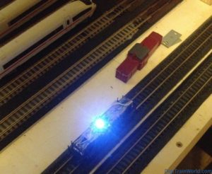
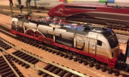
Conversion photos





I’d love it if you shared the electric diagram as well. It will help the less initiated that can still handle soldering and getting parts 🙂
Thanks for the comment! I’ve just published a more detailed post with all details (including the diagram of course), this was long overdue: http://www.locgeek.com/2015/03/using-all-susi-outputs-of-n-scale-dcc-decoders/
Let me know if that answers all questions!