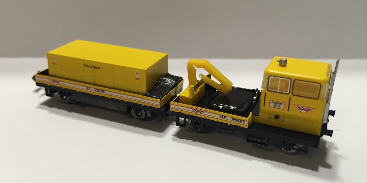
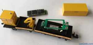
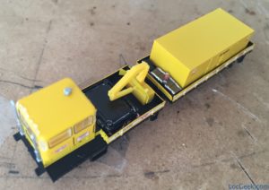
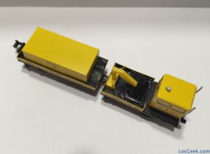
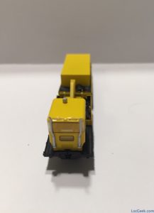
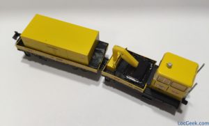
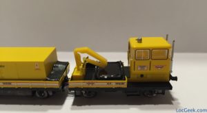
The Rottenkraftwagen KLV 53 is a funny little track work engine. As any other train in N scale, it’s even better with sound!
The model
The “Rottenkraftwagen” is a small service locomotive. Hobbytrain has released numerous versions in N-Scale, always with an accompanying car (containing the motor). I was inspired by an online video that convinced me to install sound in this model (look at the nice job they did here).
The model runs pretty well, all wheels have power feeders (the main engine is linked to the trailer with 2 wires).
Conversion goals
I decided not to install headlights (the model doesn’t have any), and concentrate on a clean installation of Doehler & Haass Next18 sound decoder, the SD18A. As you’ve seen in recent posts (here or here), I have become quite fond of the Next18 digital interface. So here was my plan:
- Remove the NEM651 digital interface, replace with a Next18 digital interface (N18-K-0 from Doehler & Haass)
- Add a sound decoder (SD18 from Doehler & Haass)
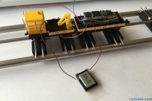
The sound project provided by D&H is actually for another engine (“Breuer tractor”), but is close enough for me. - Put the speaker in the main engine and hide it as much as possible.
Some people have managed to install a really small speaker in the trunk of the trailer. I prefer to have a better speaker, even if it is slightly visible. - Add a buffer to even further improve behaviour on dirty tracks
A word on the buffer
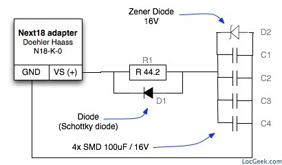
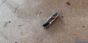
For a while now, I have included a buffer with electronic capacitors in most models. This really greatly improves the train’s behaviour. In N-Scale models, sometimes only SMD (small size) components can fit, and it is the case here. Again, the advantage of the Next18 interface is that the plus and the negative (GND) poles are available, as the norm requires, which is just what we need for a buffer circuit.
Here is schematic of the buffer circuit, FYI:
This circuit is much better explained and presented on the German website 1001-Digital, so if you speak German, read on there!
Here is a short reminder of what those pieces do:
- R1 & D1 are the “loading circuit”.
When charging, the current goes through R1, limiting the charge only slightly so the command station doesn’t think there is a short circuit.
When unloading (providing power when the track is dirty), the current can flow freely through D1 to provide emergency power to the decoder - D2 is a “Zener Diode”
It should actually never be needed. But in case the tension rises over 16V on the track, it opens and prevents anything over 16V to go through the capacitors by short-circuiting them. Since those SMD capacitors have a max rating of 16V, the Zener diode is a protection in the unlikely case the command station would go over 16V (I use 14V on my tracks). - C1 to C4
With the capacitors, in parallel : their capacity adds up (4x100uF = 400uF).
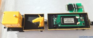
Conversion pictures
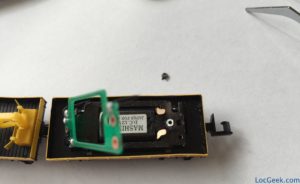
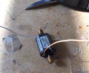
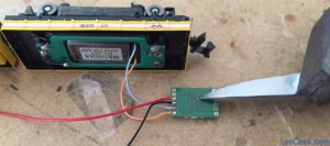
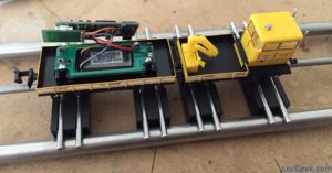
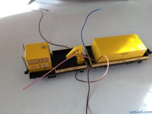
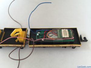
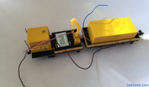
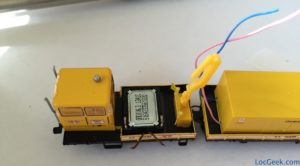
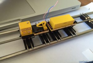
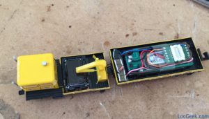
Here are all the detailed pictures that should speak for themselves. If you have questions, don’t hesitate to ask in the comments section.

